带宽B | 400 | 500 | 600 | 800 | 1000 | 1200 | 1400 | ||||||||
挡边高H | 60 | 80 | 80 | 120 | 120 | 160 | 160 | 200 | 160 | 240 | 200 | 600 | 240 | 400 | |
最小横隔板间距 | 100 | 120 | 120 | 160 | 160 | 200 | 200 | 250 | 200 | 280 | 250 | 350 | 280 | 400 | |
输送量(原煤、 带速1m/s)M 3/h | 35° | 28 | 36 | 50 | 71 | 104 | 120 | 157 | 195 | 216 | 327 | 331 | 466 | 500 | 794 |
45° | 19 | 25 | 33 | 57 | 83 | 97 | 127 | 157 | 175 | 271 | 267 | 384 | 414 | 680 | |
60° | 15 | 19 | 23 | 40 | 58 | 59 | 90 | 112 | 124 | 197 | 190 | 278 | 302 | 524 | |
90° | 9 | 11 | 15 | 21 | 31 | 37 | 48 | 60 | 66 | 106 | 102 | 149 | 162 | 281 | |
外型尺寸 | 头轮带面高H1 | 1200 | 1350 | 1615 | 1815 | 2000,2200 | 2300,2525 | 2525,2700 | |||||||
尾轮带面高H2 | 690 | 800 | 950 | 1115 | 1250,1400 | 1600,1700 | 1600,1700 | ||||||||
中间段带面高H3 | 700 | 800 | 850 | 1115 | 850,1200 | 1400,1500 | 1600,1700 | ||||||||
中间段地脚宽B1 | 580 | 850 | 1020 | 1220 | 1440 | 1690 | 1890 | ||||||||
Note: The conveying capacity in this product is calculated according to the minimum spacing between the diaphragms, the belt speed increases or decreases, and the conveying capacity increases or decreases exponentially; other materials can be determined by referring to this table.
粒度mm | 《100 | 《160 | 《250mm | ||
速度m/s | 挡边高《120mm | 倾角《30° | 2 | 1.6 | |
倾角《60° | 1.6 | 1.25 | |||
挡边高《240mm | 倾角《30° | 2.5 | 2 | 1.6 | |
倾角《60° | 1.6 | 1.6 | 1.0 | ||
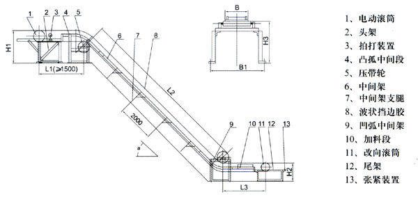
3. Appearance drawing

4. Selection
According to the characteristics of the conveyed material, the inclination angle and the conveying volume, refer to Table 1 and Table 2 to determine the belt width, sidewall height and belt speed of the conveyor. in:
(1) The sidewall conveyor belt is divided into room temperature (-20~50℃), heat resistance (below 120℃), high temperature resistance (below 180℃), acid resistance, alkali resistance, oil resistance, etc.;
(2) When conveying bulk materials, the sidewall should be high; it is also possible to increase the conveying capacity by increasing the belt speed (1.25m/s, 1.6m/s, 2m/s) without increasing the bandwidth and sidewall. ;
(3) The maximum conveying height is 70m, and the maximum particle size should be 30-40mm less than the height of the rib.
(4) The distance between the upper rollers is generally 1.2m, the distance between the lower rollers is generally 1.2m, when the inclination angle is greater than 60°, it is 2.4m, and the distance between the anti-deviation rollers is 3-6m. L3 standard is 2200, minimum 1500.
(5) The power estimation is as follows.
Concise selection calculation table of large inclination belt conveyor
带宽 B(mm) | 挡边高 H(mm) | 30° | 40° | 60° | 75° | ||||
输送量 (m 3/h) | 功率 (Kw) | 输送量 (m 3/h) | 功率 (Kw) | 输送量 (m 3/h) | 功率 (Kw) | 输送量 (m 3/h) | 功率 (Kw) | ||
500 | 120 | 52.8 | 2.85 | 63.2 | 1.86 | 26.6 | 1.32 | 19.8 | 0.98 |
650 | 120 | 77.6 | 3.97 | 55.3 | 2.6 | 39 | 1.85 | 29 | 1.35 |
160 | 105 | 5.44 | 76.3 | 3.57 | 56.2 | 2.56 | 41.6 | 1.86 | |
800 | 160 | 133 | 6.99 | 96.6 | 4.59 | 71.2 | 3.28 | 52.6 | 2.38 |
200 | 195 | 9.8 | 159.8 | 7.07 | 117.6 | 5.07 | 86.5 | 3.66 | |
Instructions for use:
1. This table is only suitable for preliminary and simple selection, and the final selection result should be determined according to the calculation results.
2. The data in this table are calculated according to the tape linear velocity V=1m/s, the distance between the diaphragms ts=0.25m, the material is the capacity γ=1t/m3, and the lifting height H=10m is calculated under the assumptions, if the conditions are different, it should be appropriate Convert.
3. Selection example:
Known: the conveying material is coal, the capacity is γ=0.8t/m3, the material particle size is A<40mm, the conveying inclination is β=45°, the conveying volume Q=85t/h, the conveying height is 15m, find the required bandwidth and belt speed and motor power. First find that the conveying capacity of the belt conveyor should be 85t/h÷0.5t/m3,=106.25m3/h, and then find the conveying capacity of B=800 and H=160 in the 45° inclination column in the table 96.6m3/ h is the closest, and then change the line speed to 1.25m/s, then the conveying capacity of the tape becomes 96.6m 3/h×1.25=120.75m 3/h, which can meet the usage requirements. The corresponding required power is 4.59Kw×15m÷10m×1.25=8.6kw.
4. The form of the diaphragm is selected according to the inclination of the conveyor;
18°<β≤40°T type, 40°<β≤60°C type, 60°<β≤90° TC type


